
Inquiry
Form loading...
-
Phone
-
E-mail
-
Whatsapp
+86 19720579616

-
WeChat
+86 19720579616

-
 Zalo
Zalo

+86 19720579616
+86 19720579616
Zalo
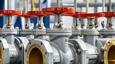
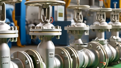
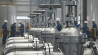
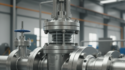
Din Bellows Sealed Valves protect demanding process systems where ordinary stem packing may release hazardous or valuable media. Their defining feature is a welded metal bellows, fitted around the moving stem inside the valve bonnet. As the stem rises or falls, the bellows flexes without exposing the process fluid to the atmosphere. This creates a sealed barrier. It also reduces fugitive emissions and limits contamination around the stem.
Valve engineer Dr. Richard W. Greene explains, “A bellows valve is only as reliable as its bellows, welds, and installation.” That practical warning matters. A strong bellows cannot compensate for poor alignment, excessive vibration, or incorrect torque. DIN Bellows Sealed Valves commonly use stainless steel or nickel-based bellows, depending on temperature, pressure, and chemical compatibility. Their bodies may serve steam, vacuum, toxic gases, heat-transfer fluids, and high-purity services. Selection still requires care.
Inside the valve, the actuator or handwheel moves the stem. The plug then controls flow through the seat. Meanwhile, the bellows compresses or extends while maintaining the primary seal. A secondary bonnet gasket may provide additional protection. Many designs also include a telltale port or monitoring connection. Small details matter here.
This article explains their construction, working principle, advantages, limitations, and maintenance requirements. It also examines why bellows fatigue can develop over time. The technology is dependable, but not magical. Wrong sizing, repeated over-stroking, or neglected inspection can shorten service life. Understanding those weaknesses helps engineers choose and operate these valves with greater confidence.
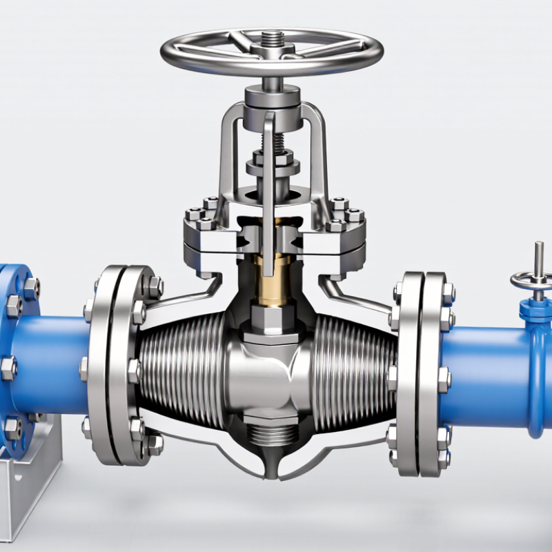
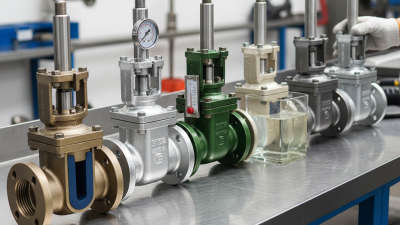
DIN bellows sealed valves are industrial valves designed to control liquids, gases, or steam without relying on a sliding stem packing seal. A welded metal bellows moves with the stem and forms a closed barrier around it. This design limits fugitive emissions, protects the medium from outside contamination, and reduces contact with hazardous fluids. DIN specifications commonly guide dimensions, pressure classes, materials, and connection details. The exact requirements still depend on the valve type and service conditions.
These valves are used in chemical processing, pharmaceutical production, district heating, power generation, and vacuum systems. They are especially valuable where toxic, corrosive, radioactive, or ultra-pure media require careful containment. The International Energy Agency’s Global Methane Tracker 2024 estimated about 120 million tonnes of methane emissions from fossil fuel operations in 2023. Bellows sealing cannot solve every emission problem, but it addresses one important leakage path. UNEP’s Global Methane Assessment also found that human-caused methane emissions could fall by 45% this decade using available measures.
The design is not magic. Bellows can fatigue under repeated movement, pressure changes, or vibration. Maintenance teams should check cycle life, temperature limits, welding quality, and actuator alignment. Real installations are rarely perfect. A valve may meet DIN dimensions yet still fail if the material is poorly matched to the process. Correct sizing and documented testing matter more than the label alone.
What DIN Bellows Sealed Valves Are and Where They Are Used
| Data Dimension | Typical or Standardized Information | How It Works | Where It Is Used |
|---|---|---|---|
| Valve Definition | An industrial valve with a welded metal bellows surrounding the stem and forming a secondary pressure boundary. | The bellows flexes as the stem moves while preventing the process medium from escaping through the stem-packing area. | Processes where toxic, flammable, radioactive, corrosive, or valuable fluids must be contained. |
| Primary Valve Type | Most commonly designed as a globe or globe-style shut-off valve; specialized designs may also be available for other flow-control arrangements. | A plug or disc moves toward or away from the seat to stop or permit flow. | Isolation duties in pipelines, process skids, utility systems, and equipment connections. |
| Stem-Sealing Arrangement | Metal bellows provide the primary dynamic stem seal. A packed gland is often included as a secondary safety seal. | The bellows absorbs axial movement without allowing the process fluid to contact the external stem area. | Low-emission service and installations with strict leakage-control requirements. |
| Main Pressure Boundary | The valve body, bonnet, welded bellows, and pressure-retaining connections form the pressure-containing assembly. | Internal pressure is retained by the body and bonnet while the bellows isolates the moving stem from the fluid. | Pressurized gas, liquid, steam, vacuum, and hazardous-fluid systems. |
| Actuation Method | Manual handwheel operation is common; pneumatic, electric, or hydraulic actuators may be used when remote operation is required. | The actuator moves the stem, causing the bellows to compress or extend and the closure member to change position. | Manual maintenance isolation, automated process control, and remote emergency shutdown systems. |
| Bellows Construction | Formed metal convolutions are designed for repeated axial movement. Stainless steel and nickel-based alloys are selected according to the medium and temperature. | The convolutions flex within a defined stroke limit while maintaining a sealed barrier around the stem. | Chemical processing, high-purity service, thermal-fluid systems, and difficult-to-contain media. |
| Flow Direction | Flow direction is specified by the valve design and body marking; globe valves generally have a preferred installation direction. | Correct orientation helps the disc, seat, and body manage pressure forces and shut-off performance. | Steam, hot-water, gas, cryogenic, and chemical piping installations. |
| Nominal Size | Common industrial sizes range from small instrument and utility connections to larger process-line valves. The available range depends on the design. | Size selection is based on required flow capacity, pressure drop, connection size, and shut-off duty. | From sampling and auxiliary lines to main process and utility piping. |
| Pressure Rating | DIN-based systems commonly use PN pressure designations, such as PN16, PN25, PN40, or higher where the valve design permits. | The allowable pressure depends on body material, temperature, bellows design, end connection, and applicable standards. | Pressure selection for chemical plants, power facilities, gas systems, and industrial utilities. |
| Temperature Capability | The operating range is application-specific and may extend from cryogenic temperatures to several hundred degrees Celsius when suitable materials and seals are used. | Material properties, bellows fatigue resistance, seat design, and actuator limits determine the safe working temperature. | Cryogenic fluids, steam, thermal oil, hot gases, and refrigerated process media. |
| End Connections | Flanged, butt-weld, socket-weld, and threaded connections may be selected according to pipe size, pressure, temperature, and maintenance requirements. | The connection joins the valve pressure boundary to the piping system while maintaining mechanical and leak-tight integrity. | Fabricated process lines, compact equipment packages, high-integrity piping, and clean-service systems. |
| Relevant DIN and EN References | Project specifications may reference DIN or EN requirements for valve design, face-to-face dimensions, flanges, materials, pressure testing, and fugitive-emission performance. | The applicable standard defines design, dimensional, testing, or performance requirements; the exact standard depends on valve type and service. | Engineering procurement specifications, plant standards, inspection plans, and regulatory documentation. |
| Leakage Control | Bellows sealing significantly reduces external stem emissions compared with a conventional packing-only arrangement, provided the bellows and welds remain intact. | The process fluid is separated from the atmosphere by a continuous metallic barrier around the moving stem. | Emission-sensitive plants, hazardous-gas service, vacuum systems, and environmental compliance applications. |
| Key Advantages | Low external leakage, reduced routine packing maintenance, improved containment, and compatibility with demanding process media. | The bellows performs the stem-sealing function without requiring sliding contact between packing and the stem during normal operation. | Hazardous, high-purity, high-temperature, and difficult-to-maintain installations. |
| Main Limitations | Higher initial cost, limited bellows stroke and cycle life, greater sensitivity to mechanical damage, and more specialized inspection requirements. | Repeated flexing creates fatigue stress; excessive travel, vibration, pressure pulsation, or incorrect installation can shorten service life. | Applications requiring careful sizing, correct alignment, controlled actuation, and planned maintenance. |
| Typical Applications | Chemical processing, petrochemical service, power generation, pharmaceutical production, vacuum systems, cryogenic equipment, and industrial gas handling. | The valve isolates or regulates flow while the bellows prevents process-fluid leakage along the stem. | Any installation where personnel safety, product purity, environmental protection, or fluid retention is important. |
Note: Pressure, temperature, size, material, cycle life, and leakage performance must be confirmed from the specific valve design, applicable standards, and the process conditions.